NAR-A121 60 GHz Radar SiP | Corezzle Electronics

Generative Hardware, SiP, Edge AI & IoT Solutions

NAR-A121 — 60 GHz Radar Sensing SiP Module™

CA-32MP2x-16GB-BGA

Click the image for an enlarged view

Prototype Stage. The NAR-A121 datasheet (Rev. 0.1) is published and available for direct download: pin map, electrical characteristics, radar RF data, power supply, mechanical and application notes.

Volume production is targeted for September 2026; you can request an evaluation sample and pricing.

NAR-A121 is an 18.6 × 15 × 1.7 mm, 30-pin castellated System-in-Package module designed for distance measurement and presence detection applications. It combines the Acconeer A121 60 GHz pulsed coherent radar sensor (57–64 GHz operating band) with the STMicroelectronics STM32L431CBY6TR microcontroller (Arm Cortex-M4F, low power) in a single package. Raw radar data is processed on the module and delivered to the carrier board over UART, I²C, CAN and GPIO. The antenna is inside the package, so the carrier board requires no 60 GHz RF design, antenna layout or trace impedance calculation. It is optimised for distance measurement, presence and motion detection, level monitoring and people counting; dust, noise, colour and lighting conditions do not degrade the measurement, and the module produces no image and records nothing. The pin 1–28 map is identical to the Acconeer XM125, so the module drops into carrier boards designed for the XM125. Pins 29–30 are the Corezzle CAN addition. Sold as a standard SiP, with project-based design services available for custom SiP variants.

Product Details

Block Diagram

Select diagram:

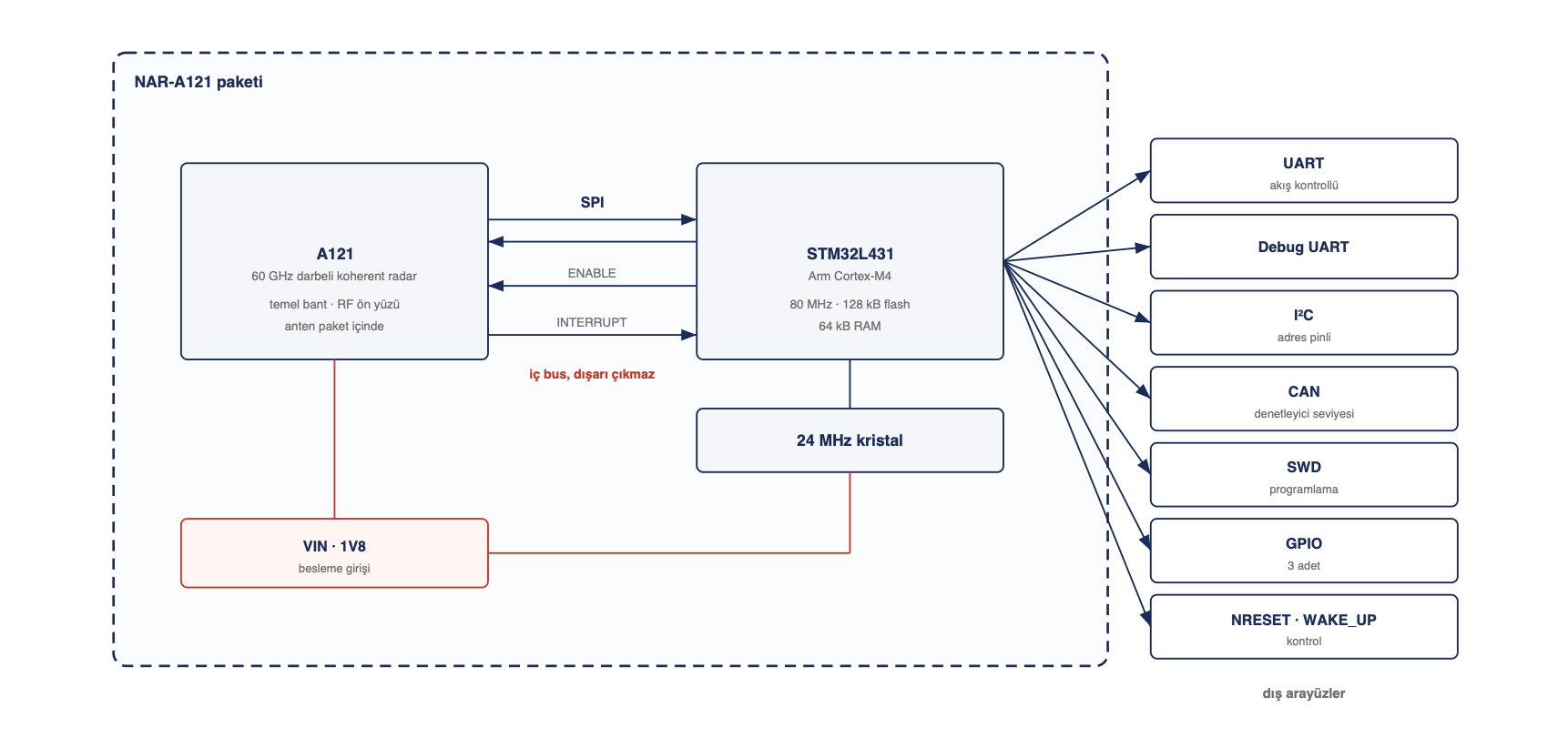
NAR-A121 SiP Module Block Diagram

NAR-A121 SiP Module Block Diagram

Integrated Components

Radar Front End

60 GHz Radar Sensor

  • Sensor: A121-001-T&R (Acconeer)
  • Technology: Pulsed coherent radar (PCR)
  • Operating band: 57–64 GHz
  • EIRP: 11.4 dBm (typical)
  • Antenna: integrated in package — no RF design required on the carrier board
  • Beam width: 53° E-plane / 65° H-plane (typical HPBW)

Processor

Microcontroller

  • Processor: STM32L431CBY6TR (STMicroelectronics)
  • Core: 1× Arm Cortex-M4F @ 80 MHz
  • Flash: 128 kB internal
  • SRAM: 64 kB internal
  • Function: processes raw radar data in-package, presents results to the interfaces

Clock

Oscillator

  • Crystal: ECS-240-8-36-RWN-TR (ECS Inc.), 24 MHz
  • System clock: up to 80 MHz via internal PLL

Power and In-Package Connection

Power Rails + Internal Bus

  • Supply rails: VIN (1.8 V or 3.3 V) + 1V8 (radar analog/digital)
  • Ground: 9 pins (2, 4, 7, 10, 13, 16, 19, 22, 27)
  • Regulator: none in package — both rails are supplied by the carrier board
  • Internal bus: SPI (radar ↔ microcontroller), inside the package, not brought out
  • Passives: in-package decoupling

Features

Hardware Specifications

  • Package: 18.6 × 15 × 1.7 mm, 30-pin castellated edge pads
  • Pins: 1.27 mm pitch, 0.90 × 1.30 mm pads (14 top + 14 bottom + 2 side)
  • Radar: Acconeer A121, 60 GHz pulsed coherent, 57–64 GHz
  • Processor: Arm Cortex-M4F @ 80 MHz, 128 kB flash + 64 kB RAM
  • Measurement range: 0.03 – 23 m (both limits conditional, see datasheet §5.3)
  • Radial resolution: 26 – 230 mm (depending on profile and temperature)
  • Supply: VIN 1.8 V / 3.3 V plus separate 1V8 analog rail
  • Temperature: −40 °C / +85 °C operating, 125 °C storage
  • Power consumption: 4.98 mW (0.25 m @ 10 Hz) — 0.04 mW (2.75 m @ 0.1 Hz)
  • Idle current: 17.7 µA hibernate / 6.9 µA off
  • Soldering: MSL 3, single reflow pass, peak 245–260 °C (IPC/JEDEC J-STD-020)

Software Specifications

  • Execution model: the application runs on the microcontroller inside the package
  • Radar processing: distance, presence and level measurement are performed on-module
  • Carrier board side: no radar driver, RF library or signal processing software required
  • Host communication: command protocol over UART (default), I²C or CAN
  • Software loading: SWD or embedded boot loader (serial interface)
  • Field update: pull pin 26 high to enter the boot loader, load over serial
  • Log output: dedicated Debug UART line

Compatibility

  • Pin compatibility: pins 1–28 are identical to the Acconeer XM125 — the module drops into carrier boards designed for the XM125
  • Extension: pins 29–30 add CAN (Corezzle addition, not present on the XM125)
  • Interface selection: single module → UART, multiple modules on one bus → I²C (address pin), long cable runs, electrical noise, multi-node → CAN
  • Delivery: standard SiP, custom SiP variants on a project basis
  • Shipping: EIA-481 compliant 24 mm carrier tape, 13" (330 mm) reel, MSL 3
  • Automotive: this product is not AEC-Q100 qualified

Interfaces

  • UART: flow-controlled (TX / RX / CTS / RTS) — primary interface, default choice
  • Debug UART: independent second serial line for development logging
  • I²C: two-wire, master and slave mode, address selection via I2C_ADDR (pull-up resistors on the carrier board)
  • CAN: at bxCAN controller level — transceiver belongs on the carrier board
  • SWD: programming and debugging (may be left as test points in volume production)
  • GPIO: 3 general purpose (MISC_GPIO2 also selects the boot source at power-up)
  • Control: NRESET, WAKE_UP, MCU_INT (measurement-ready interrupt)
  • Power: VIN, 1V8, 9× GND
  • Internal bus: SPI (radar ↔ MCU) — inside the package, not accessible from the carrier board
  • RF: antenna is inside the package, no external antenna or u.FL connection

Development Environment

  • Programming: SWD — development and production line
  • Alternative loading: embedded boot loader over serial interface (pin 26 high)
  • Debugging: dedicated Debug UART line
  • Minimum connection: VIN + 1V8 + GND + UART_TX/RX — five signals are enough
  • Reference design: an evaluation board reference design will be published (supply, interface connections, CAN transceiver, radiation path mechanics)
  • Scope note: the internal schematic of the package is not part of the delivery, the product is delivered as a packaged chip

Documentation

See document types for quick access

Filter
Categories

6 document